The desk finds the page scale
The desk reads the scale when you open a plan PDF: AutoCAD viewports, scale text, and letters drawn as lines. Confirm one known dimension, then measure.
Typing the scale on every sheet is the slow part of takeoff, and it happens before you measure a single foot.
Open a multi-sheet architectural set and each page wants the same ritual: find the title block, read 1/4″ = 1′-0″, notice the enlarged plan is 1/2″, notice the detail bubble is something else, type it, then do it again on the next sheet. Miss one viewport and the guardrail LF is in the wrong universe while the number still looks clean.
The desk reads those callouts when you open the Document. Plan viewport, detail viewports, scale text, and scale letters that were drawn as lines. You are not walking the title block on every page to learn what the scale is. You confirm one known dimension, then you measure. That is the time you get back on a set.
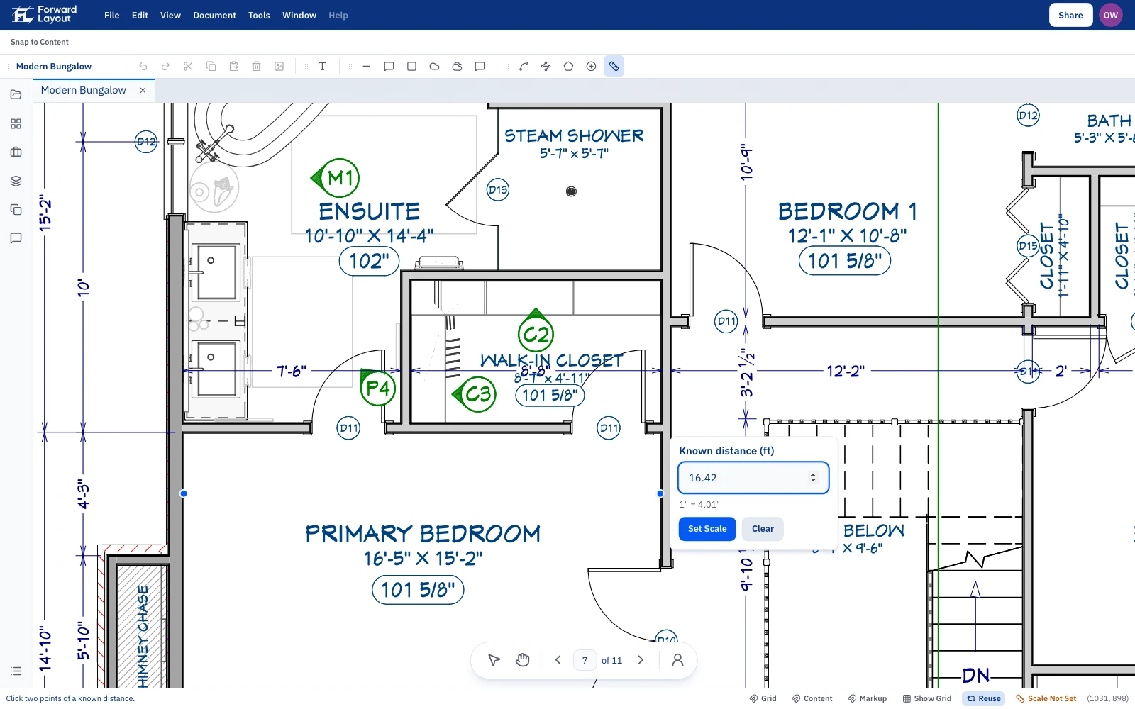
Where this lives
Open a Project, open the Document, and the read runs with the file. It is not a separate upload step and not a button you have to remember.
The status bar still says Scale Not Set until that page has a confirmed scale. Length, Polylength, and Area do not compute a length without it. The read tells you what the sheet says. Calibrate is how you confirm it. The measuring loop is still how it works.
AutoCAD viewports
A plotted sheet is often several views, not one scale. The floor plan sits at 1/8″ = 1′-0″. A stair detail on the same page sits at 1/2″ = 1′-0″ or 1 1/2″ = 1′-0″. AutoCAD stores those as viewports. Each viewport has its own scale, and the callout is printed on that view.
The desk finds each callout and where it sits on the page. The same phrase twice, apart on the sheet, stays two hits. A detail at half-inch does not become the scale for the plan beside it.
That is the classic wrong-units failure: one scale for the whole page, then a Length inside the detail reports inches as feet, or the reverse. You still name the view you are measuring. The hunt for what the bubble says is the part you skip.
Scale text, and letters drawn as lines
Two kinds of scale show up on a PDF from CAD.
Text. The words are real PDF text. SCALE: 1/4″ = 1′-0″, 1:100, 1:50, N.T.S. The desk reads those phrases and leaves lookalikes alone: a slope note, a legend column of abbreviations, a title-block “as shown” that is not a view scale.
Vector. CAD often plots the scale with stroked letters instead of a font the PDF can select. SHX text, outlined text, a scale equation drawn as linework. There is no text layer to copy. A markup desk that only reads the text layer reports no scale. You zoom in, squint, and type it on every one of those sheets. The desk clusters those strokes back into the scale phrase, including 1/4″ = 1′-0″ and a metric ratio such as 1:100, and including N.T.S. so a not-to-scale detail is not treated as a measured view.
Viewport scale in the text layer is common. Scale letters that are only lines are the sheets that still cost the afternoon, because the usual tools never see them.
When the sheet is only a picture
A scan, a flattened plot, or a phone photo can leave the scale as pixels. No text layer. No letter strokes. Some of those plots look raster and are still vectors: the letters were outlined, and the vector read above still finds them. When the scale is only pixels, the desk does not invent a scale, and it does not assume letter paper and imperial feet because the file opened.
Calibrate on a drawn dimension you believe: two clicks, type the real length. Then measure something else that already has a dimension and see if it matches. A scale bar that photocopied into mush is a bad segment. Two dimensions that disagree: stop and resolve them. Do not average them into a scale the building does not have.
Why that check exists, and what wrong scale looks like when every LF is off by the same percent: why scale calibration matters.
What you still check
- Open the Document. Let the file finish opening so the read can run.
- Look at the view you are about to measure. Plan and detail are not the same scale.
- Calibrate on a longish known dimension on that view. A grid you trust. Not a tiny tick.
- Measure a second dimension that is already on the sheet. Tool says
19′-6″and the drawing says20′-0″: wrong endpoints, the wrong viewport, or a distorted sheet. Fix it before you run hundreds of feet of guardrail. - Then Length, Polylength, Count, and Area. Name the Subject. Totals stay in the Markups List.
Skip the confirm and the LF can look precise and still be wrong. The formatting is not the length.
If the read misses
Scale Not Set on the status bar means this page has no confirmed scale. Click it and Calibrate. Do not measure anyway.
A title block that says “as shown,” a field that is a date, or a slope written as 1:12 is not a sheet scale. The reader is built to leave those alone. If the only scale on the sheet is a picture, Calibrate from a dimension.
N.T.S. and not-to-scale details are not a scale you can measure with. Use the viewport that has a real scale, or Calibrate that view from a known length.
Related
Confirming the number is why scale calibration matters. The loop after that is how it works: measure, Markups List, CSV. Stairs and rails on an honest scale: stair and railing quantities. The file you opened is a Document inside a Project.
Straight answers
- Does the desk set the scale for me?
- It reads the scale callouts on the sheet when you open the Document, including more than one viewport. You still confirm a known dimension before you trust an LF. If the page has no readable scale, the status bar stays Scale Not Set and Length will not compute.
- What if one sheet has a plan and details at different scales?
- Each AutoCAD viewport keeps its own scale. A 1/8″ plan and a 1/2″ detail on the same sheet are two callouts. Measuring inside the detail uses the detail scale, not the plan scale.
- What if the scale letters are not selectable text?
- A lot of CAD plots draw the scale as lines (SHX and outlined text) instead of a PDF text layer. The desk reads those strokes. A desk that only reads text misses them, and you type the scale by hand.
- What about a scanned sheet or a phone photo?
- If the scale is only pixels, with no text and no letter strokes, the desk does not invent a scale. Calibrate on a drawn dimension. A picture of a title block is not a measurement.
- Do I still Calibrate?
- Yes. Confirm a known length on the view you are about to measure. The read callout saves the hunt. The check is what keeps the LF honest. Skip it and every length can look precise and still be wrong.